Software Architecture Document
Table of Contents
- Introduction
- Architectural Representation
- Architectural Goals and Constraints
- Use-Case View
- Logical View
- Process View
- Deployment View
- Implementation View
- Data View
- Size and Performance
- Quality
1. Introduction
1.1 Purpose
This document provides an overview of our software architecture. With several architectural views it depicts different aspects of the system. It is intended to capture and convey the significant architectural decisions which have been made for the system.
1.2 Scope
This document describes the architecture of the FileFighter project.
1.3 Definitions, Acronyms and Abbreviations
| Abbreviation | Explanation |
|---|---|
| SRS | Software Requirements Specification |
| UC | Use Case |
| n/a | not applicable |
| tbd | to be determined |
| UCD | overall Use Case Diagram |
| FAQ | Frequently asked Questions |
| API | Application programming interface |
| MVC | Model view controller |
| REST | Representational state transfer |
| VCS | Version control system |
| nas | Network Attached Storage |
| CI/CD | continuous integration continuous delivery/continuous deployment |
| TDD | Test Driven Development |
1.4 References
| Title | Date | Publishing organization |
|---|---|---|
| FileFighter Blog | 13.10.2020 | FileFighter |
| FileFighter Github | 13.10.2020 | FileFighter |
| UC Login | 13.10.2020 | FileFighter |
| UC Register | 13.10.2020 | FileFighter |
| UC View folder contents | 13.10.2020 | FileFighter |
| UC Edit permissions | 13.10.2020 | FileFighter |
| UC Edit profile | 13.10.2020 | FileFighter |
1.5 Overview
This document contains the architectural representation, goals and constraints as well as the logical, deployment, implementation and data views.
2. Architectural Representation
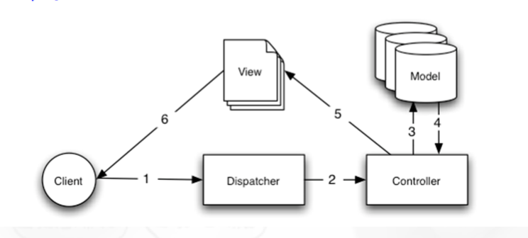
This project uses the MVC Pattern for the back end (Spring Boot). So the model (data model, domain specific classes), the view (user interface), and the controller (controls the Application) are separated. The MVC Pattern can be seen in the next picture:
 source: Wikimedia Commons
3. Architectural Goals and Constraints
Our architecture is based on microservices. Microservices are defined as independent small applications, that serve a special purpose. This gives us the ability to develop each service independently and even with different technologies.
To be able to setup and deploy the whole application we will be using Docker. That way we can manage CI/CD, pipelines, and different versions of the services independently. The main reason for using Docker is how easy it is to use as a Client. The dependencies needed to host the whole application are reduced to only docker. Furthermore, all the typical advantages of Docker apply here.
We will develop three microservices.
Our frontend where all the interaction with the normal user will take place, will be developed with the JavaScript library React. It will be hosted in a container and provide a web user interface.
The second service is a RESTful Web service that will handle the users and abstract a filesystem. The information about the individual users and all their files will be stored in a MongoDB database. The web interface will provide the frontend with all the needed information about folders and their content for authenticated users, but not the actual files.
The actual files will be handled by the “DataHandler Service”. This service will provide a interface to store and receive files. The files will be stored on disks. When the users tries to download or upload a file the “DataHandler Service” will also communicate with the RESTful Web service to guarantee authentication.
The whole architecture is also outlined in figure 1 for an easier overview.

For the authentication we will be using two kind of tokens. One with an longer active time an one with an shorter one. When the user logs in with his username and password he will get a Refresh token, which has s longer active time an can be saved in the browser (with cookies for example). With this Refresh token he then will be able to request Access Token, those only last a short amount of time, but are necessary for all the Api requests involving the sensitive data. The backend will connect each Access Token with the correspondent user and make sure the user only has rights to access what he is supposed to be able to access. This process is also outlined in figure 2.

In order for our client to easily install our application we will provide docker images for all our services.
Those images will automatically be build for every release using GitHub Actions and published on a container registry.
The client will then just need to build and start the containers. All this will be done automatically by a script we will provide in our ClientSetup repository. The script will initialize all necessary services, start the FileFighter nas and also periodical check for new versions of the services.
The deployment process is also displayed here.
MVC
As mentioned already, our back end is written in Java. As an addition we are using the framework spring as well as the library Spring Boot. One advantage of this usage is that Spring Boot and Spring are implementing the MCV software architecture by themself. As a database we use MongoDB. The Server offers multiple REST APIs which are accessed by our front end. MVC:
- Model: domain specific classes
- View: domain specific classes serialized to JSON format.
- Controller: Multiple Controllers for different Use Cases
4. Use-Case View

4.1 Use-Case Realizations
n/a
5. Logical View
5.1 Overview
Our application contains multiple services. Our front end consumes the views provided by our SpringBoot Backend and transforms them into a valid user interface. The front end application handles all the user interaction and independently handles the view coordination thus fulfilling the roles of view and dispatcher alike. However view and dispatcher do not interact with the client independently instead the dispatcher has been substituted by the ViewModel which connects the view and the model as described above as well as forming the connection to the controller.
More specifically we are using a slightly more detailed logic that can be seen here:
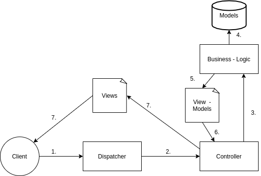
The main difference is that we use View-Models and Data-Models. View-Models, often called “DataTransferObjects” (DTOs), are instances of classes that are made for the customer / user of the endpoints. The Data-Models, often called “entities”, are a representation of the data that is stored in the database. Entites are never leaked to the consumer and thus are never directly manipulated. Our business logic is transforming the entities to DTOs and visa versa, to be able to encapsulate certain information like passwords. In our specific case the views, provided by the back end, consist of the information stored in the DTOs formatted with the JavaScriptObjectNotation(JSON). However, the frontend does not interact with the model itself. Model classes are duplicated into the fronted for consistency reasons but are only used to populate the corresponding views. Any actual manipulation of the view model is handled by the backend.
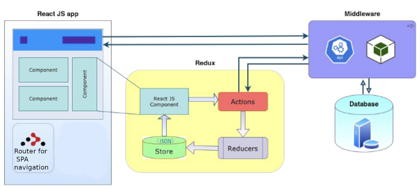
To populate the corresponding views the frontend will store the data using Redux. After requesting data from the backend the frontend will dispatch action with the data. Those actions will then be processed by reducers and written to the JSON store. The views will then take the data from this store.
5.2 Architecturally Significant Design Packages
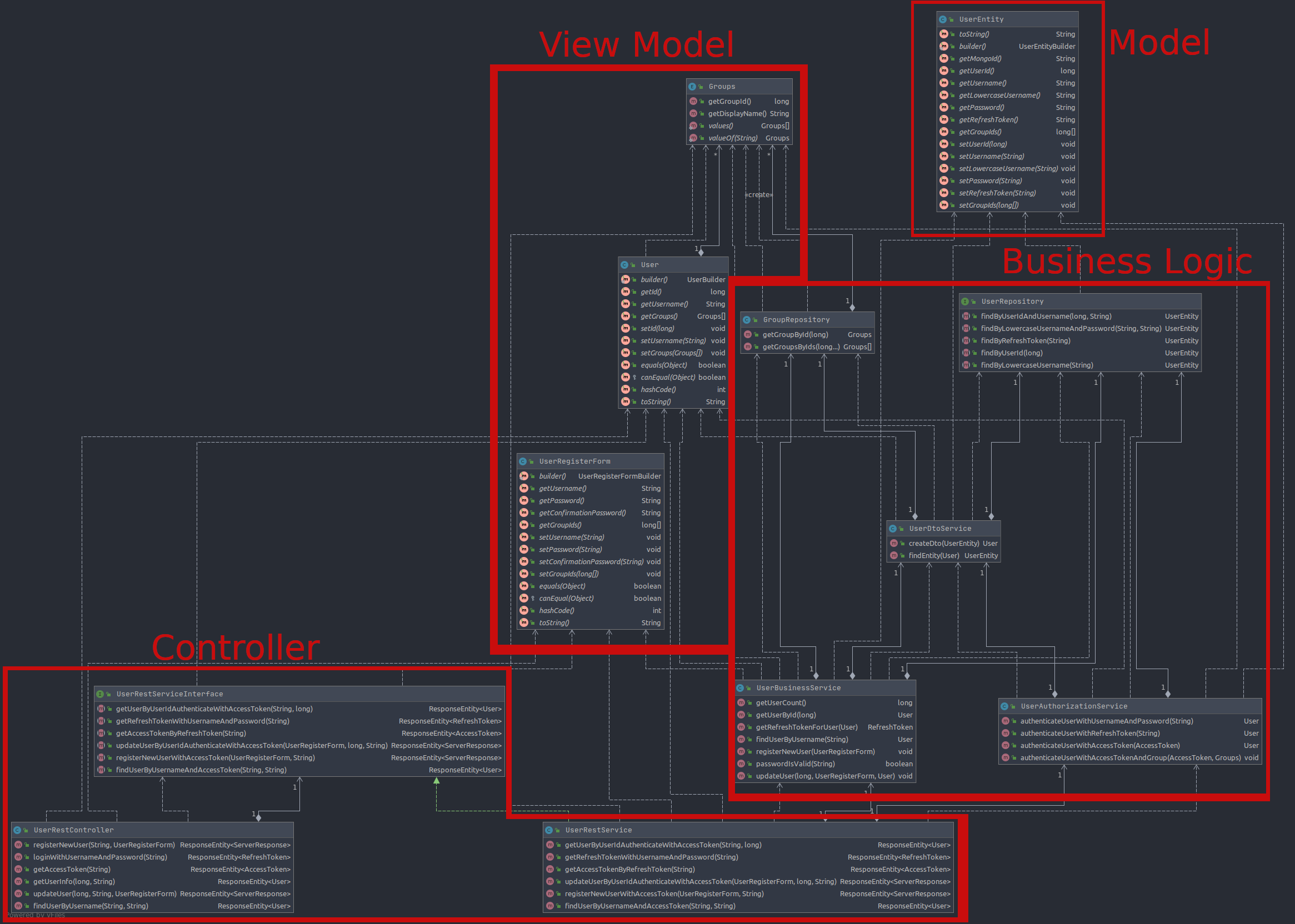
On this section you can find our class diagrams for the backend. We have clearly marked which parts fulfill the model, the view and the controller tasks.
The different domains contain a view model often called DTO, “Data-Transfer-Object”, as well as the models, called “Entities”, that are persisted in the database. We highlighted the DTOs, Entities, and the controller parts. Below you can see one of our class diagrams for the back end. In this case it’s the class diagram for the domain “user”. For visibility reasons we removed, test-, builder- and exception- / exception handler classes.
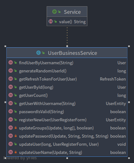
We implemented the SOFA design pattern for the UserBusinessService, the refactored Class Diagram is shown below. In the large Diagram the Service is located in the bottom right of the Business Logic block.
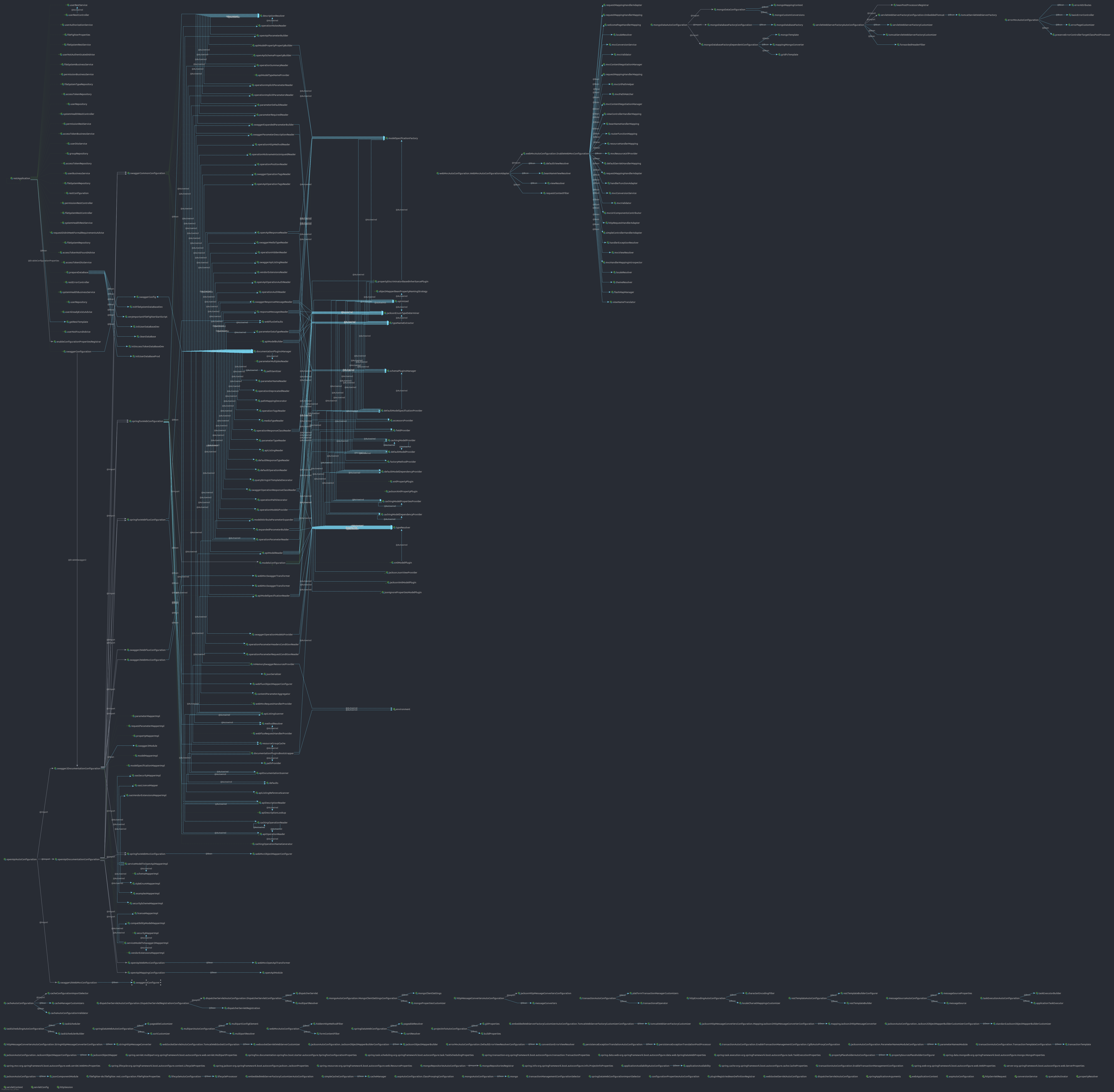
The full class diagram is displayed here. Click on the image to enlarge it.
6. Process View
n/a
7. Deployment View
Here you can see our deployment view diagram:

And here the flow of realising new versions.

8. Implementation View
n/a
8.1 Overview
n/a
8.2 Layers
n/a
9. Data View
Database ER-Diagram:

10. Size and Performance
n/a
11. Quality/Metrics
The application is being measured in terms of complexity, coupling and cohesion. Due to the MVC Pattern the backend is unproblematic regarding any of these metrics. The web application makes it more difficult to achieve similarly good metrics for the frontend. Handling the UI elements requires many method calls from framework classes, contexts and views have to be handled and passed which increases all the above mentioned metrics. However, we have committed to still avoid high ratings in these categories even though we could not prevent several classes to be rated medium-high.
Our Code in front and back end is constantly check by our own instance of SonarQube. The back end is also providing a “health” endpoint, that is displaying status information about data integrity, uptime, user count, used storage and more. This way the customers can see this information via the endpoint or via the metrics provided by our front end.
Leave a comment on our blog:
Comment on our blog below or open an issue on our Github repository.